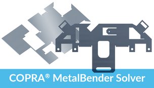
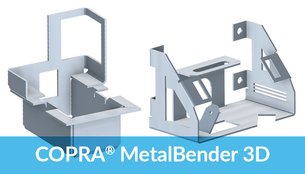
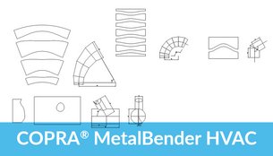
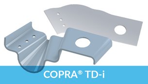
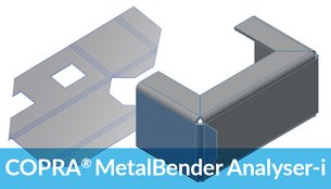
deutsch


COPRA® MetalBender TD·i
Sheet Metal Application f
or Inventor®
Sheet Metal Lofting · Transitions · Sheet Metal Part Library · Flat Pattern Calculation

data M Software sheet metal technology is integrated into the Autodesk Inventor® functionality for sheet metal part design. Many powerful sheet metal features are already available for the professional designer.
To enhance the existing design features and as an addition to the already existing technology for press brakes data M now also offers a solution for transitions, e.g. for HVAC applications.
The COPRA® Metal Bender TD·i is very easy to use and takes into account the specific requirements of sheet metal parts.

All in one

  • Extensive library containing standard sheet metal parts for HVAC applications

  • Automatic creation of standard transitions circular-rectangular-rounded

  • Special features for designing any contours – SheetMetal Lofting

  • Powerful flat pattern calculation for rounded and sharp-edged sheet metal parts with:

COPRA® MetalBender Analyser·i


Sheet Metal Part Library

The TD·i Library consists of standard parts as used in HVAC applications. 
All sheet metal parts are precisely calculated on a parametric basis as are the intersections of more than one sheet metal part. You can select the parts from a clearly designed catalogue. The parameters offered are shown in sketches making classification very easy.

COPRA MetalBender for Transitions and Ducting - Part Library All kinds of combinations of intersections concerning cylindrical parts and conii can be created with the standard transition command in COPRA MetalBender

Previewing parameters can be switched on or off. The designer is able to work within the design context. COPRA® MetalBender TD·i has the following characteristics:

Automatic creation of sheet metal parts
All designed parts are fully parametric
Automatic creation of the corresponding assembly
Flat pattern calculation for each individual part
All parameters of the flat pattern calculation for each individual part are pre-set.

For example, all kinds of combinations of intersections concerning cylindrical parts and conii can be created with the standard transition command. The TD·i Library is ready to use from the very first minute due to its easy handling, correct parameter settings, automatic creation of sheet metal parts and pre-set calculation parameters. All this results in a very short amortisation period.

The following parts are available:
Segment elbow
Transition with offset
Cylindrical pipe with rectangular branch
Dished boiler end with horizontal branch pipe
Ventilator cowl
Conus with cylinder
Pyramid with cylinder
Pipe branch with cone
Pipes
Dished boiler end with circular base
Pipe with oval branch
Transition


Standard Transitions

Standard Transitions in COPRA MetalBender TD-iAll kinds of combinations of circular, rectangular or rounded transitions can be selected from a clearly designed dialogue window and they are subsequently automatically created as bendable parts. Sharp-edged transitions can also be easily combined with rounded flanges.


Sheet Metal Lofting

For heating, air-conditioning and ventilation applications it is often necessary to design 3D parts consisting of two different contours. Autodesk Inventor offers a lofting feature for this purpose.
However, models that are created with this feature cannot be unfolded as the Inventor lofting command does not result in creating a bendable part. For production it is, however, essential to have a precise flat pattern calculated. data M Software now offers a unique new solution for this requirement:

The SheetMetal Lofting feature.
User friendly dialogue in COPRA MetalBender TD-i (Transitions and Ducting)  Transition - COPRA MetalBender Td-i

The procedure is comparable to the standard lofting command in Inventor. It differs however in the very fact that it takes the specific requirements of sheet metal parts into account.
The user will – in any case – get a truly bendable part based on sheet metal technology. Step by step the integrated dialogue assistant leads the user to the final desired result. All parts that have been designed with the SheetMetal Lofting feature can be modified by using Inventor® commands and are later unfolded with COPRA® MetalBender Analyser·i.

SheetMetal Lofting design approach:
Step 1: Design of boundary contours

First the two boundary contours (2D contours) are created with Inventor® functionality.

The following parameters can be defined:
Selection of the boundary contours
Definition of the cutting gap width
Position of cutting gap on contours
Standard setting for number of bending edges of an arc
Automatic division of contours, e.g. of a circle

Step 2: Bending lines
In the second step the user determines the positions of the bending lines. The corresponding elements are clearly shown in a dialog box and can be modified at a later stage.

Step 3: Calculation of 3D solid
A 3D solid is now calculated according to the defined parameters.

The following definitions can now also be made:
Material thickness (sheet metal thickness)
Creation of a surface or solid model
Definition of direction into which the solid is to be extruded
Result:
Bendable part according to sheet metal know-how and technology
All essential bending lines are included
Reworking with Inventor® possible
Flat pattern calculation with CMB Analyser·i


Software requirements

The COPRA® MetalBender TD·i is available for: Inventor®  from Autodesk.
The Autodesk product Inventor® is not included in delivery of the COPRA® MetalBender TD·i.


deutsch     english  | remote-support | Sitemap | contact us
Add this site to your favorites (Microsoft Explorer)

data M Sheet Metal Solutions GmbH  .  Am Marschallfeld 17  .  D-83626 Valley/Oberlaindern, Germany
Fon: +49 (0) 8024 640-0  .  Fax: +49 (0) 8024 640-300

Internet: http://www.datam.de  .  e-mail: datam@datam.de
Copyright © data M Sheet Metal Solutions GmbH  .  All rights reserved  .  Subject to change without notice
imprint / masthead